Description
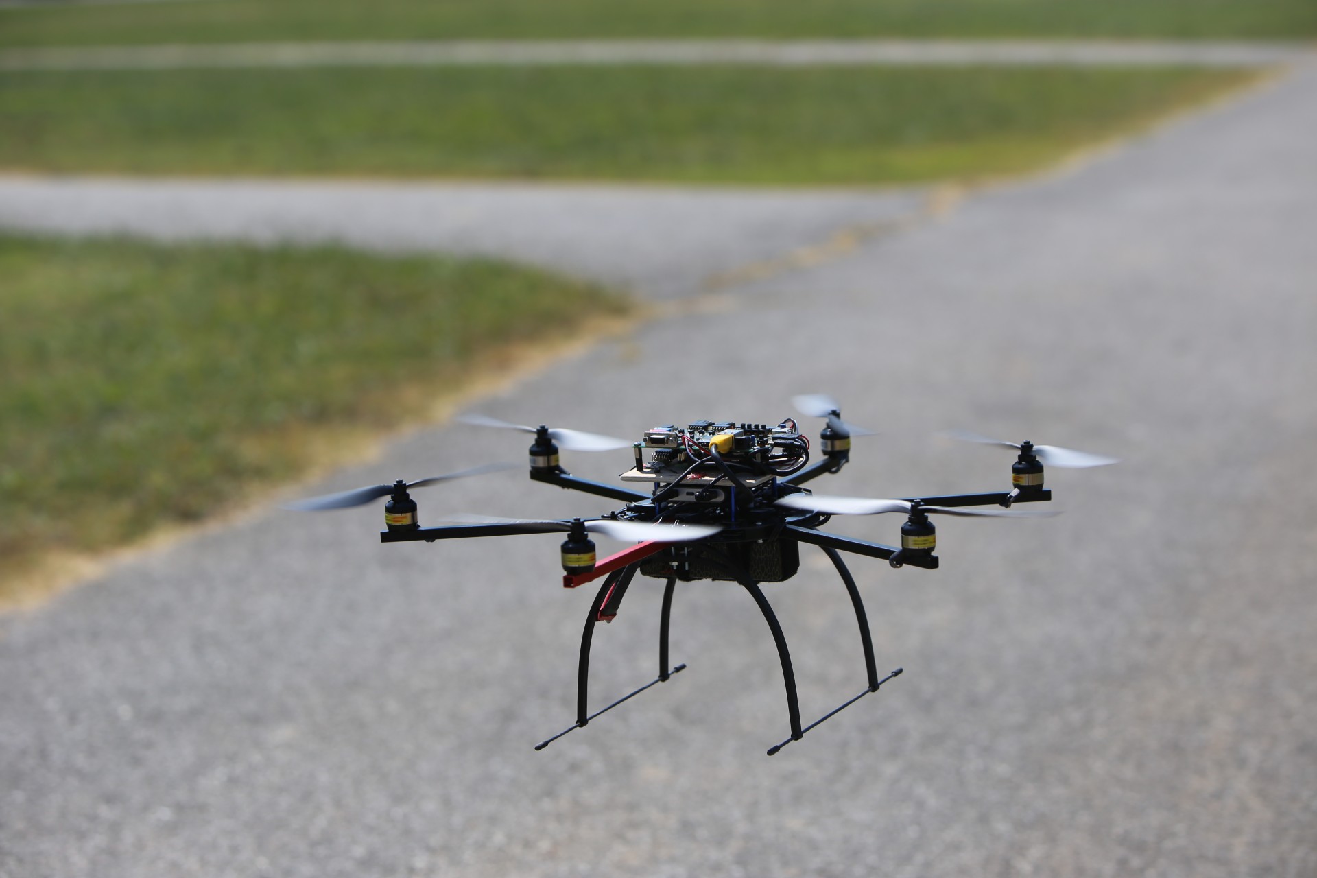
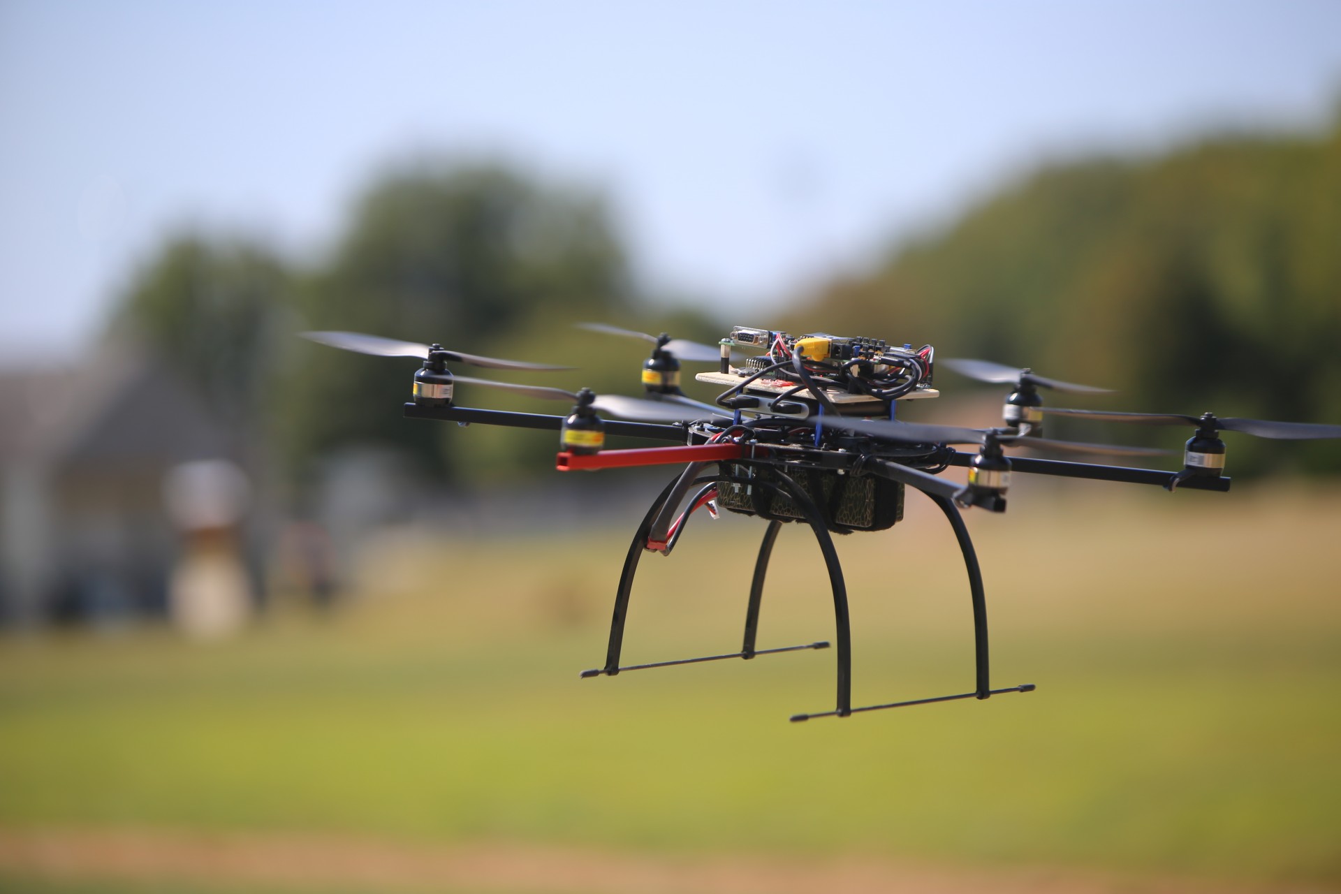
We have developed a multi-copter research platform in order to further our research into unmanned systems. The project was started in order to provide a general framework with which future research may use as an unmanned aerial vehicle platform. The ZyboCopter is the prototype platform consisting of a hexa-copter body and a Zybo FPGA serving as the flight controller. The platform is customizable to fit any application for multi-copters, planes, rovers, and submarines. The onboard FPGA system provides avenues for developing software, kernel, and hardware applications.
This is the first iteration of our research copter platforms.
Overview
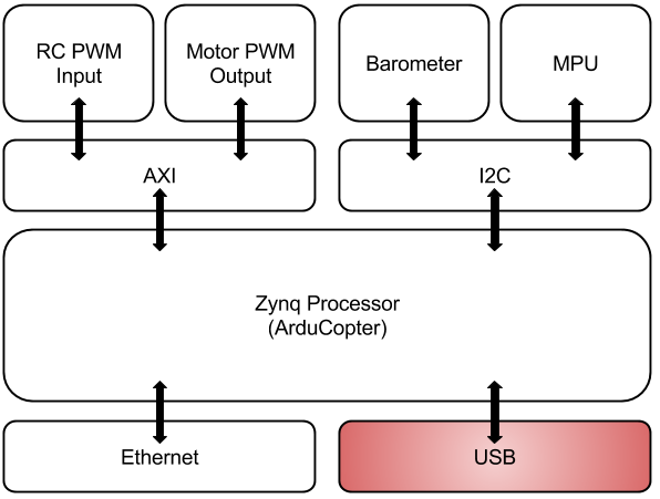
To elaborate on the specifics of the ZyboCopter platform, we utilize a basic hexa-copter frame (including six ESCs and motors) along with a Zybo FPGA acting as a flight controller. A high-level layout of the ZyboCopter is seen in Figure 1. The FPGA hardware design is derived from a base design for the Zybo. This exposes many peripherals to the onboard Zynq processor, such as Ethernet, USB, and I2C ports. Also included are two small AXI-enabled IP implemented for the purpose of converting incoming radio control (RC) PWMs to values and outgoing motor controls to PWMs. The processor is booted with a Linux kernel generated with Xilinx’s Petalinux software. The filesystem, also generated from Petalinux, is replaced with a more powerful Debian OS distribution, specifically Debian 9 Stretch. The filesystem was replaced in order to ease Linux interaction with the inclusion of several command line tools and package managers. Acting as the top level control of the prototype platform, ArduCopter manages all interactions with flight-critical hardware. ArduCopter is the multi-copter program of ArduPilot. It is worth noting again that ArduPilot allows us to apply the control programs rovers, planes, and subs in addition to multi-copter platforms. All that is required is the physical vehicle equipped with applicable hardware. This is of particular interest for a generalized unmanned systems exploration platform.
Software
The ArduCopter flight controller software is a recent fork of the ArduPilot development repository hosted on GitHub. ArduPilot consists of a set of shared libraries utilized by each of the vehicle classes. There were not many changes that needed to be applied to ArduCopter source code, but the ArduPilot libraries regarding the Hardware Abstraction Level (HAL) for linux devices were modified to use and access the two PWM IP discussed below. Board configurations for the Zybo needed to be specified according to the underlying hardware design also discussed below. Such specifications included model, I2C bus ID, and I2C address for the MPU, barometer, and compass peripheral hardware.
ArduPilot devices also require a mission planning software to utilize advanced flight modes. ArduPilot utilizes the command protocol MAVlink in order to communicate with compatible ground station software. Of particular interest is Mission Planner, which has developed along with ArduPilot. This software allows an interactive GUI to help with first-time setup, set flight paths/modes, change internal parameters, and most importantly, monitor flight status with telemetry data. A command line argument supplied when running ArduCopter allows you to push MAVlink commands over preferred interfaces, for instance a TCP socket. The ZyboCopter platform utilizes the TCP channel in order to communicate with Mission Planner via network interfaces.
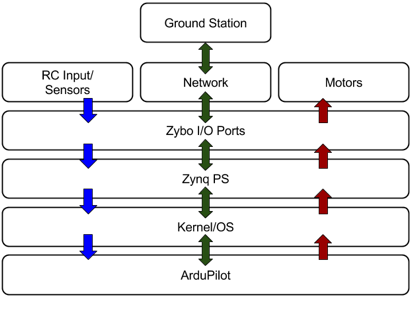 High Level System Layout
Though autonomous flight was not the focus of this project, we wanted to ensure it was enabled by the selected flight controller option. Luckily ArduPilot has integrations for range-finders and proximity sensors for future research. Additionally, ROS integrations exist to expose an extensive amount of open-source robotic communication, mobility, mapping, and image processing algorithms.
Hardware
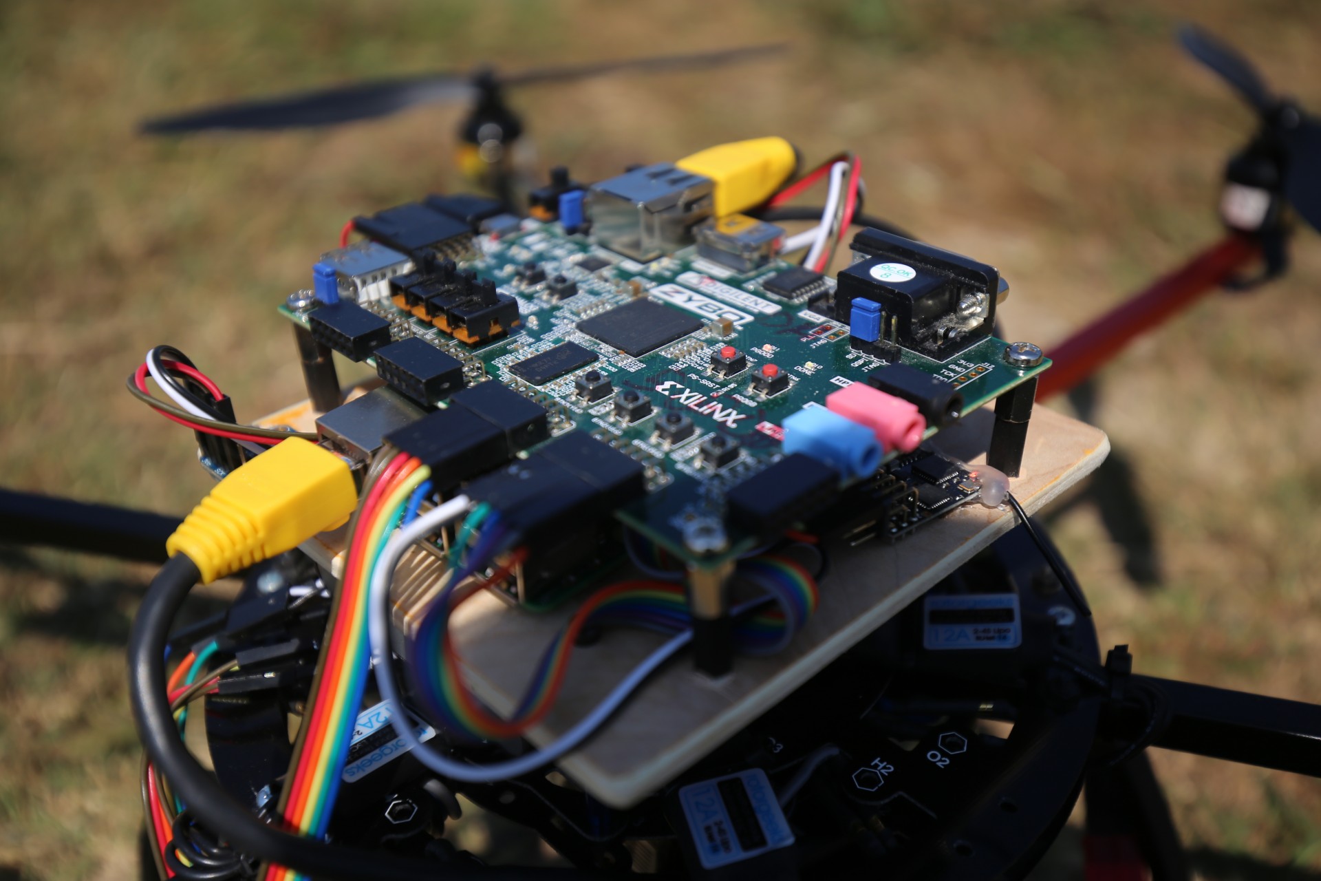
As mentioned above, the hardware design is modification of the base Zybo design. The base design provides peripherals such as Ethernet, but in order to provide the upper-layer OS and software the appropriate channels of communication, the USB port is enabled and two I2C buses are mapped to the Zybo’s external PMOD ports. Both the BMP280 barometer and MPU-9250 are connecting to the available I2C ports. The final peripheral requirements are the ESCs/Motors and RC receiver.
Due to the method with which ArduCopter originally accessed RC input signals, a PWM decoder module was implemented. This inclusion was also resultant from the available receiver hardware only providing PWM signals. ArduCopter simply does not have the ability to read a PWM signal quick enough to determine the duty cycle length. The flight controller’s RC input processing is capable of handling various signal types but always converts each signal channel to a value in the range of 1000-2000. With an output frequency of 50Hz (20ms period, 1-2ms duty cycles) for RC control signals from the receiver, ArduCopter’s internal rc_loop running at 100Hz cannot possibly derive one of a thousand possible duty cycle lengths. The fastest loop, used for inertial sensing, is 400Hz which is still very much lacking. The resolution required (1000 values over 1ms range) calls for at least a 1MHz clock. The PWM Decoder IP takes as input the PWM control signals and utilizes the Zybo’s internal 125MHz clock to derive the control signal’s value. Without regard for IP efficiency, the decoder divides a counter (incremented by the 125MHz clock cycles during PWM duty cycle) by 125 in order to reach the appropriate resolution for ArduCopter. The values are transferred to memory via the AXI bus where ArduCopter may read them.
To satisfy the final peripheral requirement, ESCs/Motors, a second AXI-enabled peripheral was added to supply PWM signals to each ESC/Motor set. ArduCopter supplies a PWM specification to memory, though the specification explicitly listed output period and duty cycle length. For the sake of symmetry, ArduCopter was modified to place only a motor control signal value in memory while the PWM Encoding IP generates a corresponding PWM signal to be sent to the ESCs/Motors. The ESC’s typically respond to a varying signal frequency, though 50Hz is standard. Thus, we utilized the calculated 1MHz reference clock to measure the duration of the output PWM’s duty cycle.
 Hardware Design
In the development process, Ethernet connections to remote machines hosting the ground station software or Xilinx TCF debugging with SDK were used. It was necessary to upgrade this method to wireless for flights, thus the Zybo’s USB port was targeted for a WiFi USB dongle. In attempting to implement this, it was discovered that there is a bug regarding the USB port’s 5V power supply. An alternate solution was devised with a Raspberry Pi serving as a network bridge. Utilizing an existing WiFi network, the Pi will connect and provide port forwarding services. That is, the Zybo is connected to the Pi’s Ethernet subnet and port forwarding is enabled for specified ports in order to allow WLAN to subnet access. Ports 1243, 1534, and 3000 were used for ArduCopter MAVlink commands, Xilinx TCF agent, and SSH respectively. The ZyboCopter’s SSH port was changed to 3000 in order to avoid an SSH collision with port forwarding and provide both the ZyboCopter and Pi separate SSH channels. This solution is currently adequate, though WiFi has a number of downfalls that other communication methods may alleviate. This is a topic of future improvements for the platform.
Photos