
Description
We have utilized the Arlo Complete Robotic System by Parallax as the physical framework for our research into autonomous ground vehicles. This kit, which can be bought here, includes a frame, motors, wheels, optical encoders, a power distribution board, a motor controller, and a Parallax Activity Board. However, as is tradition with our research, we opt to replace the Activity Board with a much more capable FPGA SoC.
The intent of this platform is to handle the evaluation of a number of robotic algorithms. Specifically for this iteration, the focus is autonomous mapping and obstacle avoidance.
Software
The software side of this platform utilizes a custom built Linux kernel built with the Xilinx Petalinux software that is booted on the Zynq processor. This allows for an easy generation of a kernel that is appropriate for any of the custom hardware implemented in programmable logic. A base Ubuntu 2018.4 LTS (Bionic Beaver) filesystem is used to complete our operating system.
Playing a central role in the software is the Robotic Operating System (ROS) in order to enable a well-organized control system. Currently with our selection of Ubuntu 2018.2, we are using the latest distribution (at this time) ROS Melodic Morenia.
Robot Description
As discussed over on the ROS page, the robot description given in the form of a URDF file makes for the organization of the robot’s links and joints. Our Arlo robot description file can be found here. This is an adaptation of the URDF file created for the ArloBot. Our file differs slightly though we do borrow the ArloBot description’s caster wheel STL file for a complete visualization in RViz.
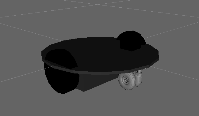
A side view of the Arlo robot model in RViz. We do not visualize the top plate or the standoffs.
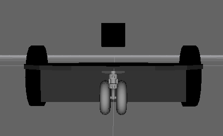 A front view of the Arlo robot model in RViz. We do not visualize the top plate or the standoffs. Notice the black box representing the laser floating above the base plate. This is due to the laser currently being mounted to the top plate that is not visualized.
For the Arlo robot, the primary transformations needed are from the laser scanner frame to the robot base frame, both wheel frames to the robot base frame, and lastly, the robot base frame to the static map frame or ground. The former two are static as the laser and the wheels are both mounted to the robot base frame. The final robot base frame to map frame transformation can be determined by dead-reckoning odometry from wheel encoders or more sophisticated odometry methods using the laser scanner.
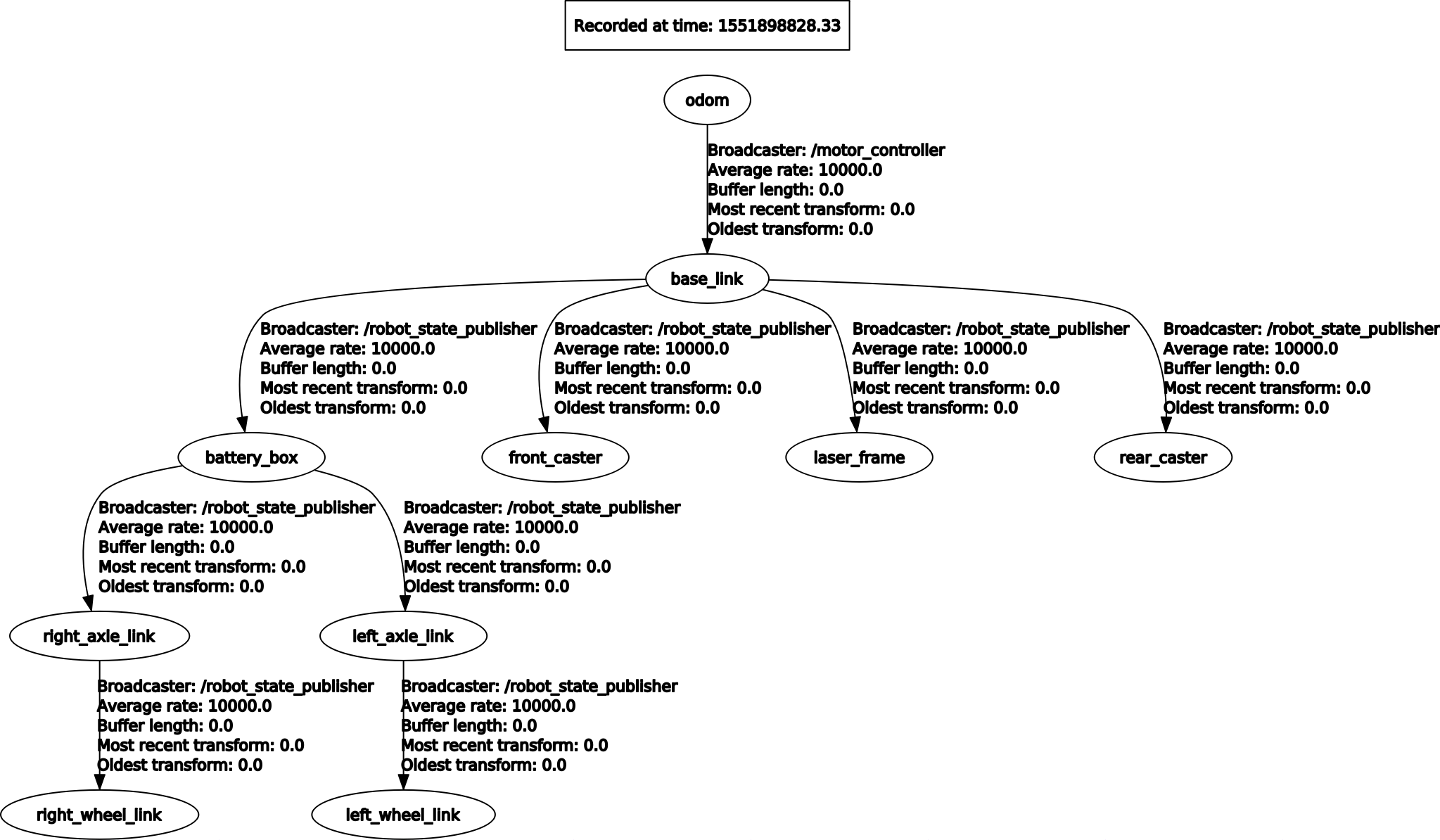 This local TF tree denotes the relationships written in the robot description URDF file. In addition, it shows the odometry frame that is not listed in the URDF file and is served by our joint interface for the Arlo robot, the motor_controller node.
Motor Controller Interface
We have made a ROS node capable of communicating with motor controller board that comes with the default configuration of the Arlo. This motor controller communicates via serial to the Zybo SoC. It is capable of receiving a stream of speed commands as well as responding to speed requests. Speed commands are issued when received while the wheel speed readings are requested in a configurable period loop.
Considering the cmd_vel command is the target message for listening for locomotion commands we need to convert the velocities received in the frame of the base_link to velocities for both the left, v_left, and right, v_right, wheel of the Arlo. Being specific, we will receive a linear velocity vx, vy, and vz and rotational velocities rx, ry, and rz for defining the linear and rotation velocities in the x, y, and z dimensions, respectively. Considering the robot is non-holonomic and does not move in the z dimension, we are only interested in vx and ry.
For converting the robot frame velocity to separate wheel velocities, we use the following equations:
# Definitions
# v_left = current left wheel velocity
# v_right = current right wheel velocity
# wheelbase_radius = distance from the center of the robot to the wheel
# enc_pos_per_sec = constant for conversion between encoder
# positions per second to meters per second
# Wheel velocities
v_left = (enc_pos_per_sec * vx) – (enc_pos_per_sec * rz * wheelbase_radius)
v_right = (enc_pos_per_sec * vx) + (enc_pos_per_sec * rz * wheelbase_radius)
With the robot setup being a differential drive, we can use the forward kinematics equations below to estimate the position of the robot at the next time step. This is done in order to issue the odometry message. Here we get the pose and orientation. See ROS odometryfor how this message is structured.
# Definitions
# v_left = current left wheel velocity
# v_right = current right wheel velocity
# d = distance between both wheels
# vx = current linear velocity, x dimension (robot frame)
# rz = current rotational velocity, z dimension (robot frame)
# theta = current heading (robot frame)
# odom_vx = current linear velocity, x dimension (odometry frame)
# odom_vy = current rotational velocity, z dimension (odometry frame)
# dt = time between previous position reading and now
# Velocities in the robot frame (Linear/rotational motion)
vx = (v_right + v_left) / 2
rz = (v_right – v_left) / d
# Velocities in the odometry frame (Positional/rotational motion)
odom_vx = vx * cos(theta) – vy * sin(theta)
odom_vy = vx * sin(theta) + vy * cos(theta)
# Current pose of robot can be obtained with Forward Euler Integration
current_x_position = previous_x_position + odom_vx * dt
current_y_position = previous_y_position + odom_vy * dt
current_z_rotation = previous_z_rotation + rz * dt
RPLidar
We use the RPLidar A1 on the Arlo Autonomous Ground Vehicle to produce two-dimensional point-maps. The ROS package rplidarfor handling the interaction with the laser scanner and retrieving a LaserScanmessage.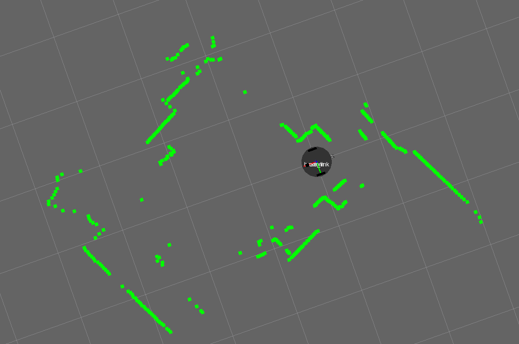 Example of a scan using the RPLidar ROS package and RViz to visualize.
Hardware
Complete list of current hardware:
- Arlo Complete Robotic System
- Digilent Zybo Z7 7010 SoC
- RPLIDAR A1 Rangefinder
- USB WiFi Dongle (Realtek 8192CU Chipset)
- Four port USB 2.0 Hub, with external power supply port
As mentioned above, this iteration of our research platform includes a frame, motors, wheels, optical encoders, a power distribution board and a motor controller. The motor controller will handle the interpretation of the encoder signals and is the primary interface for control, configuration, and status updates of the motors.
The FPGA SoC we chose for this application is the Digilent Zybo Z7 board with the Zynq7010 SoC onboard.
Without any internal wireless chipset, we needed to include a USB WiFi dongle in order to utilize the wireless networking stack in our Linux kernel and subsequently for ROS and other user applications.
For perception, we are currently evaluating the versatility of a single two-dimensional 360 degree laser range-finder or lidar. We are using the Slamtec RPLIDAR A1, available here. This communicates with our FPGA over USB connected to the onboard Zynq processor running our Linux distribution. The default serial baud rate is 19200 but can be increased to 115200 for faster transfer rates. In our case, we are currently maximizing this to ensure we are able to quickly issue motor speed commands and request motor speed updates.
Digilent support documentation for Zybo Z7 warns that many USB devices will exceed the current limit set by the SoC circuitry. As we are using more than one USB device, we selected a USB hub capable of accepting an external power supply. The Arlo power distribution board provides a number of power connections, one of which was utilized to provide a stable 5 volts at maximum 2 amps.
Pictures
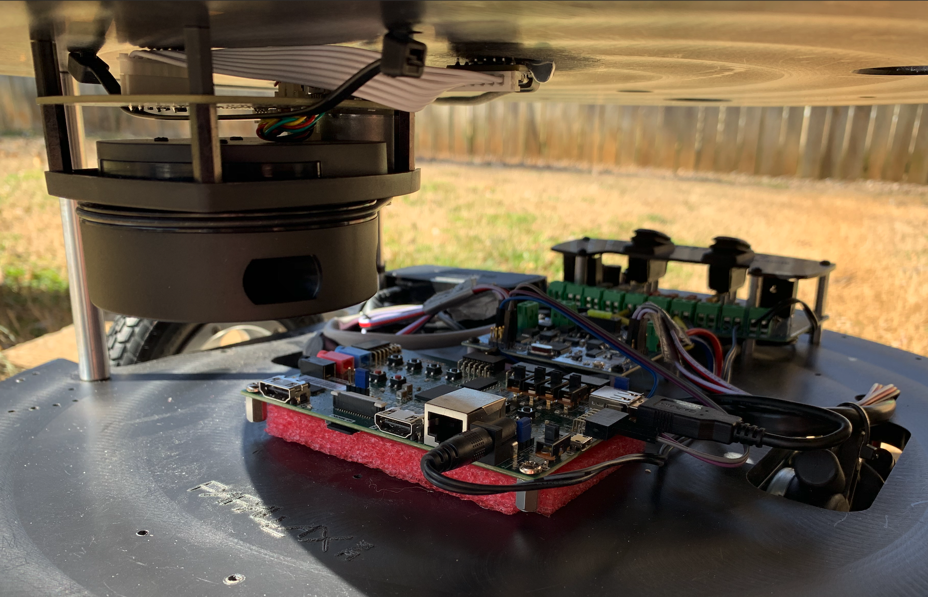 Our Arlo setup with the ZyboZ7 SoC board as the primary control board.
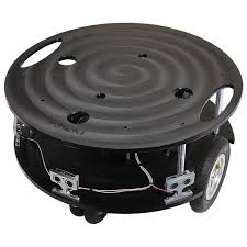 Arlo Complete Robotic System Base Configuration